

Page7
Having trouble with your Metro heater fan speed resistors in your LIBRA then change to electronic control.
(The same Kit can be used to give dual headlight function on the latest Triumph Tiger M/C).
You can use a Velleman Kit K8004 (£9.34/ www.rapidonline.com Part Code 70-4076)
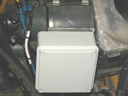
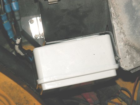
DC to Pulse width Modulator, with a DS1869-010 (10K ohm version) digital potentiometer IC attached (£3.50/Maplin). Both fit in a box 55x105x45mm (blue shown in photo) but later I used a larger box with waterproof gasket built in 100x100x50 (Grey) (Maplin code YM90X £3.99)
easier
to remove lid to adjust the initial settings.
Capable of switching 6.5Amp DC, fan motor is rated at 5Amp.
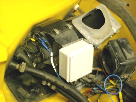
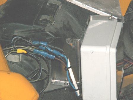
I am going to locate it on the front of the heater box as the Metro
origonal
suffered from
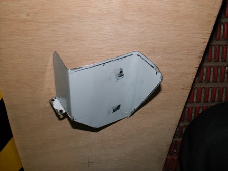
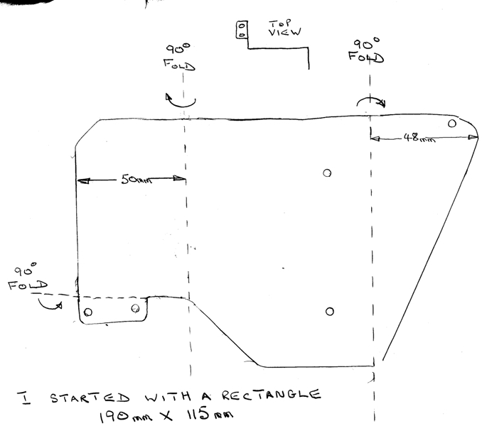
water from the windscreen etc. I used a piece of stainles steel sheet
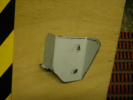
190x115mm cut to shape see sketch/photos below.
Aluminium sheet (1mm or 2mm thick) would do just as well, but I
happened
to have a piece of stainless leftover
from a cooker hood ducting trim.
There
are various ways in which the K8004 can be controlled -1K pot or a
DS1869 single push button mode or a DS1869 two push button mode, if you use the DS1869 IC the origonal
heater control wiring can be used
via the push button(s) to earth
or the origonal Metro switch to
avoid
changing the wiring, if you used the origonal Metro heater control panel as we did
(see below).
The off position will not be used, position I will be the "lower speed" control, position II will be the "last action" position, position III will be "raise speed" position.
It works like this - turn switch to I & the DS1869 will slowly lower the speed to minimum in 100ms steps (or off if required).
- turn switch to II & the speed change will stop at the current speed control point.
- turn switch to III & the DS1869 will slowly raise the speed to maximum in 100ms steps.
Cooling is a major problem in this area of the car as the radiator hot air passes through to exit at the back edge of the "bonnet".
This modification has been in place for more than two years - I have yet to open the control box to see if there are still any overheating problems. The car has been from SHEFFIELD to GLASGOW & back with additional outings to the NSC (national Space Centre).
As a point of interest any 1/4" male female connectors used are smothered in Waxoyl to make them water resistant.
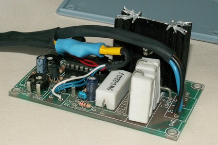
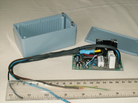
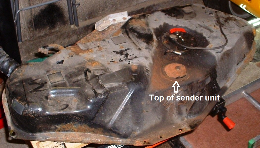
DS1869 IC is in the blue heat shrink tubing. A different box is used on final unit, photo coming soon showing external heatsink.
The off position will not be used, position I will be the "lower speed" control, position II will be the "last action" position, position III will be "raise speed" position.
It works like this - turn switch to I & the DS1869 will slowly lower the speed to minimum in 100ms steps (or off if required).
- turn switch to II & the speed change will stop at the current speed control point.
- turn switch to III & the DS1869 will slowly raise the speed to maximum in 100ms steps.
The
unit is now fitted to the car, more photos below.
IN CAR TESTING THREW UP A PROBLEM, WITH OUR INSTRUMENT PACK (NONE GTM/METRO) THE REV COUNTER RESPONDED TO THE FAN SPEED, WHEN THE IGNITION WAS ON BUT THE ENGINE WAS
NOT RUNNING. WE WERE GLAD WE USED THE LARGER BOX AS THERE WAS A NEED TO FIT AN INDUCTOR COIL IN SERIES WITH THE +12V SUPPLY, TO PREVENT SPIKES GETTING BACK ONTO THE +12V BATTERY WIRING.
WE ALSO FITTED ADDITIONAL 1000mF & 100nF CAPACITORS ACROSS THE SUPPLY ON THE K8004 AS FURTHER SUPPRESSION MEASURES. THIS HAS CURED THE PROBLEM.
IN CAR TESTING THREW UP A PROBLEM, WITH OUR INSTRUMENT PACK (NONE GTM/METRO) THE REV COUNTER RESPONDED TO THE FAN SPEED, WHEN THE IGNITION WAS ON BUT THE ENGINE WAS
NOT RUNNING. WE WERE GLAD WE USED THE LARGER BOX AS THERE WAS A NEED TO FIT AN INDUCTOR COIL IN SERIES WITH THE +12V SUPPLY, TO PREVENT SPIKES GETTING BACK ONTO THE +12V BATTERY WIRING.
WE ALSO FITTED ADDITIONAL 1000mF & 100nF CAPACITORS ACROSS THE SUPPLY ON THE K8004 AS FURTHER SUPPRESSION MEASURES. THIS HAS CURED THE PROBLEM.
September 07 - the K8004 output FET burnt out (this caused the heater fan to run at Max speed), overheated by the adjacent back EMF diode (6A2) also causing burning of the PCB. To hopefully cure the problem a new kit K8004 was purchsed, the output FET has been transfered to an external heatsink mounted on the lid of the box & an additional 6A2 diode has been connected (externally) to the wiring loom near the motor.
Cooling is a major problem in this area of the car as the radiator hot air passes through to exit at the back edge of the "bonnet".
This modification has been in place for more than two years - I have yet to open the control box to see if there are still any overheating problems. The car has been from SHEFFIELD to GLASGOW & back with additional outings to the NSC (national Space Centre).
As a point of interest any 1/4" male female connectors used are smothered in Waxoyl to make them water resistant.
DS1869 IC is in the blue heat shrink tubing. A different box is used on final unit, photo coming soon showing external heatsink.